Microelectronic sample preparation challenges
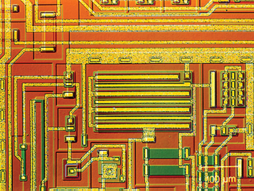
There are three main challenges when performing controlled material removal and target preparation of microelectronic samples.
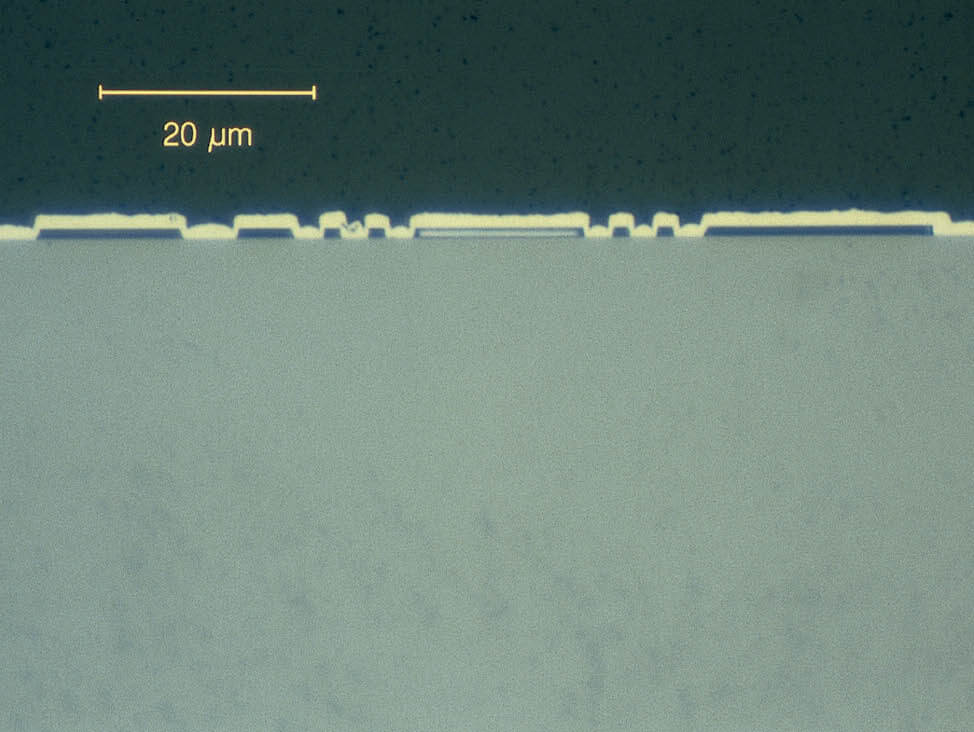
The miniature dimensions require specialized equipment and accessories suitable for handling small samples. Steps such as cutting and grinding require greater accuracy than normal, due to the dimensions, which are usually in the µm range.
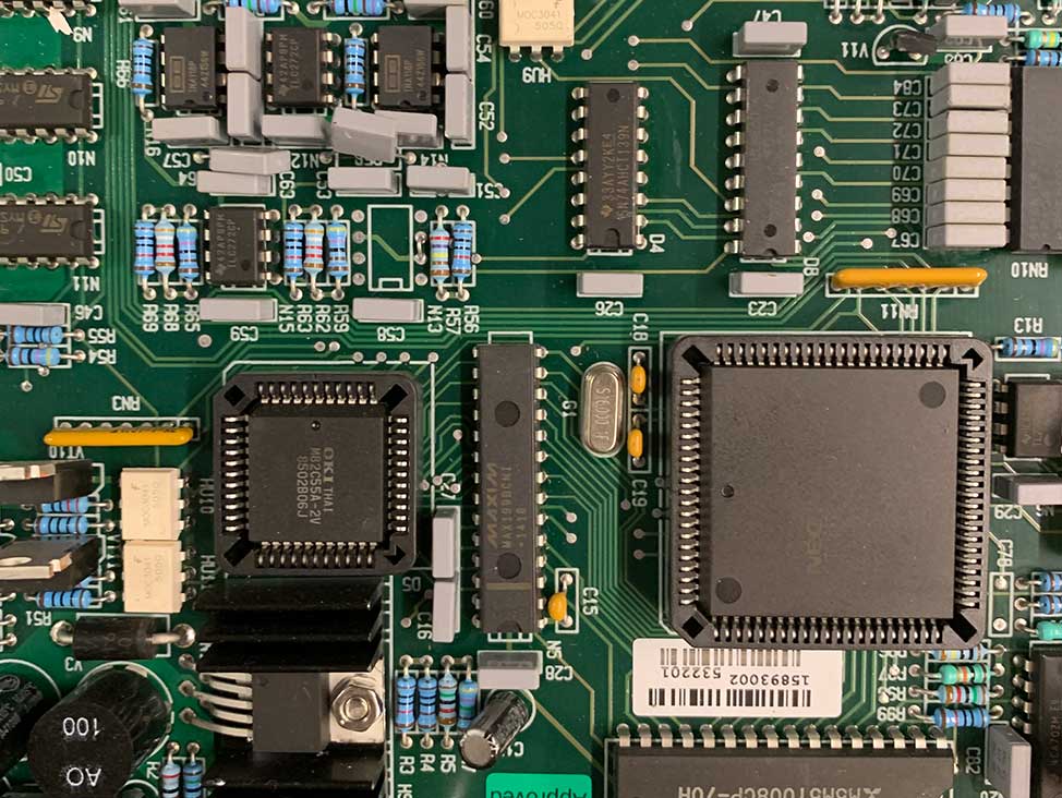
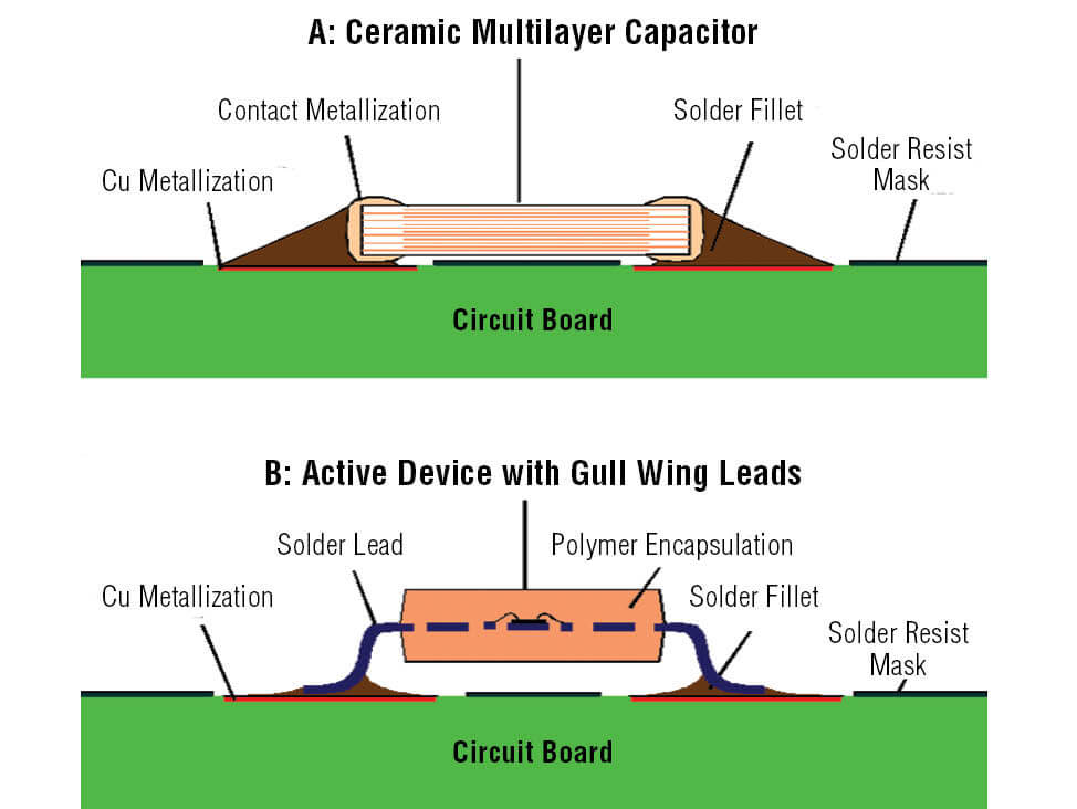
Complex material compositions are common in microelectronics, where soft metals, ceramics and composites are often closely packed. This makes the choice of preparation methods and parameters a compromise, carefully selected to meet the specific requirements.
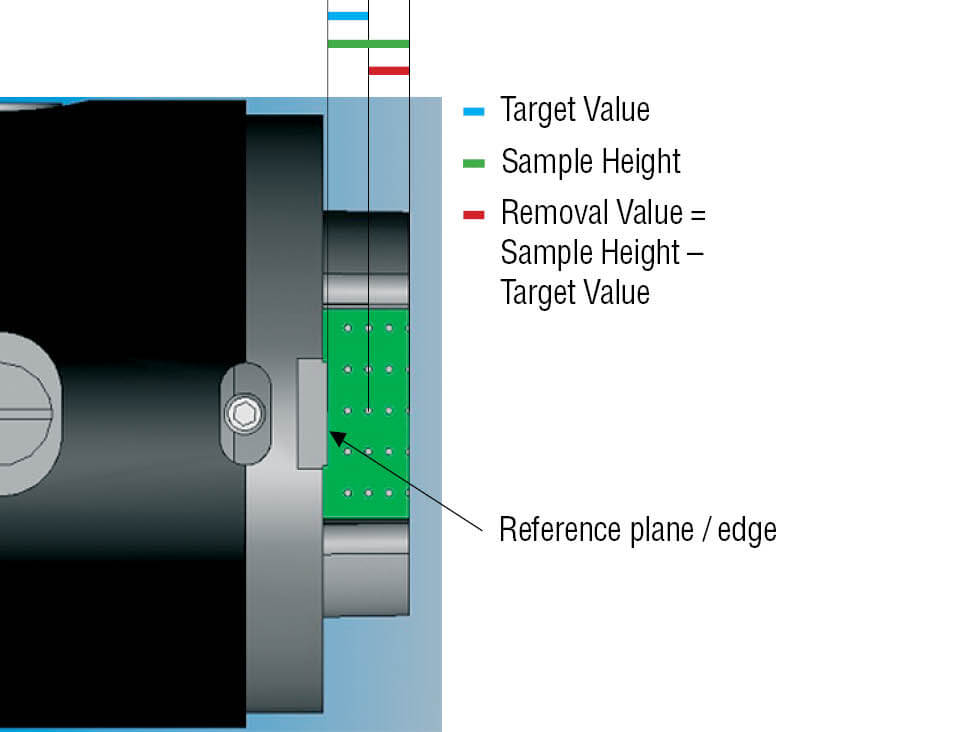
Controlled material removal and accurate preparation are needed when small targets are the subject of the examination. A metallographic sample inspection often includes looking at a particular area inside a package of interconnected chips. This can be time consuming, as it typically involves a manual controlled material removal process known as ‘grind-and-look’ (i.e. repeatedly grinding and then checking until the target appears and is ready to be polished).
In research or failure analysis, missing the target during a grind-and-look process can mean losing a unique and/or costly sample. Therefore, automated or optimized solutions are increasingly used due to their high mechanical precision, optical measuring units and mechanical stops.
Common difficulties during the preparation of microelectronic samples, include:
- Cutting: Chipping and cracking of silicon wafers, glass or ceramics
- Mounting: Mechanical deformation and thermal damage
- Grinding: Fracture of brittle constituents such as glass fibers or ceramics
- Polishing: Smearing of soft metal layers; relief due to the difference in hardness of different materials; silicon carbide and diamond particles remaining in solder
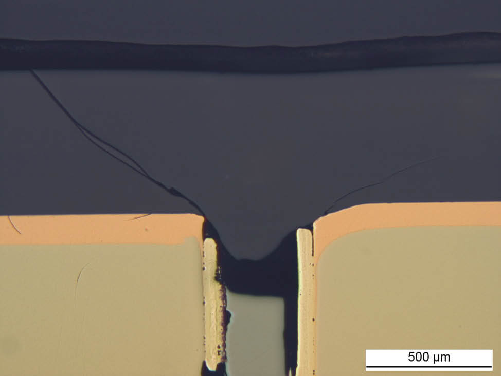
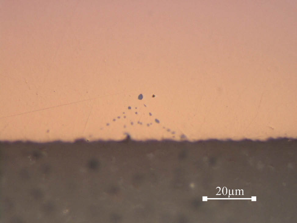
Fig. 7: Detection of a crack in a diode
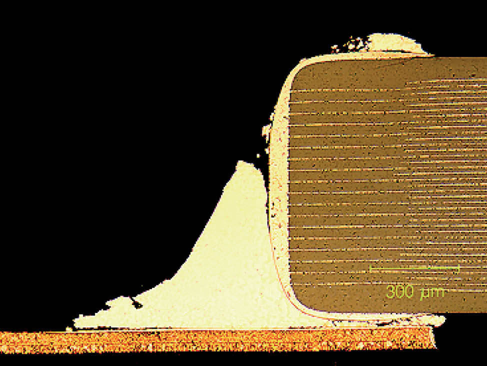
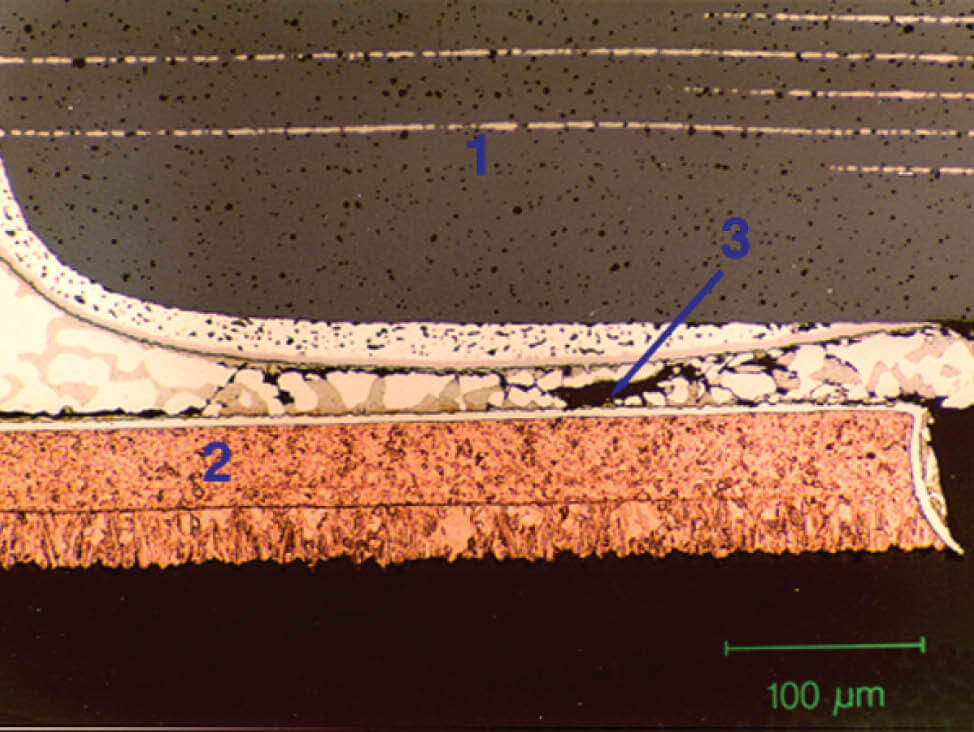
Fig. 8: Through section of an aged ceramic multilayer capacitor with fatigue cracks in the solder connection
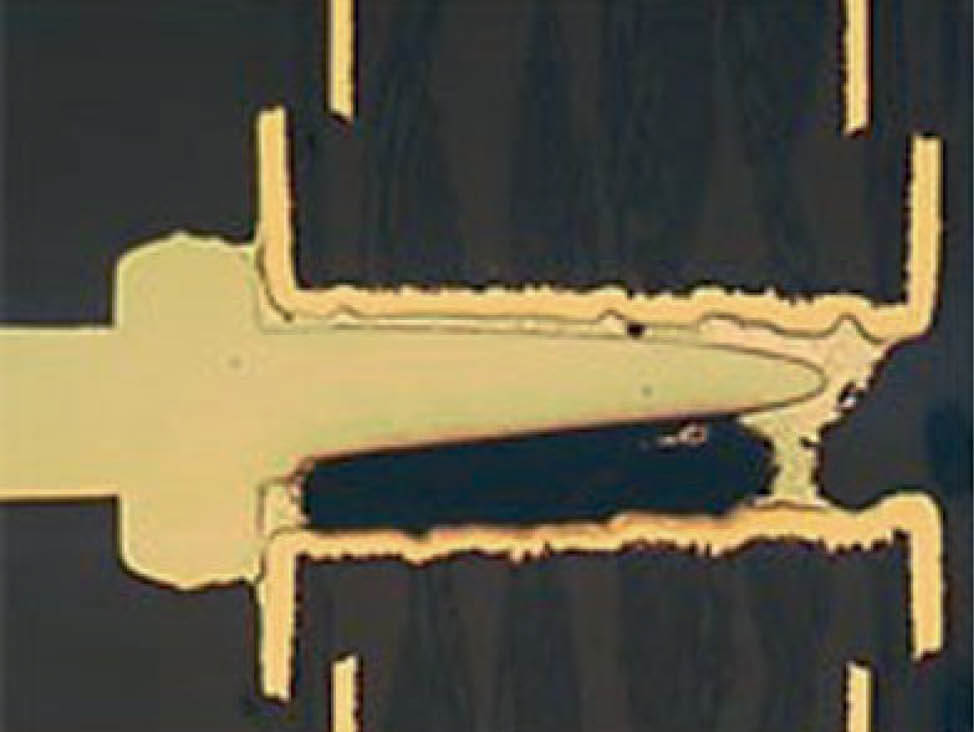
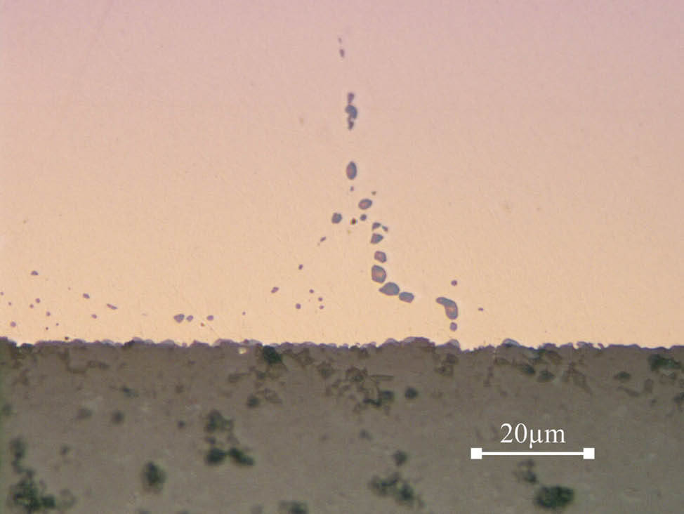
Fig. 9: Large void in the solder of a plated through-hole connection (50 x)
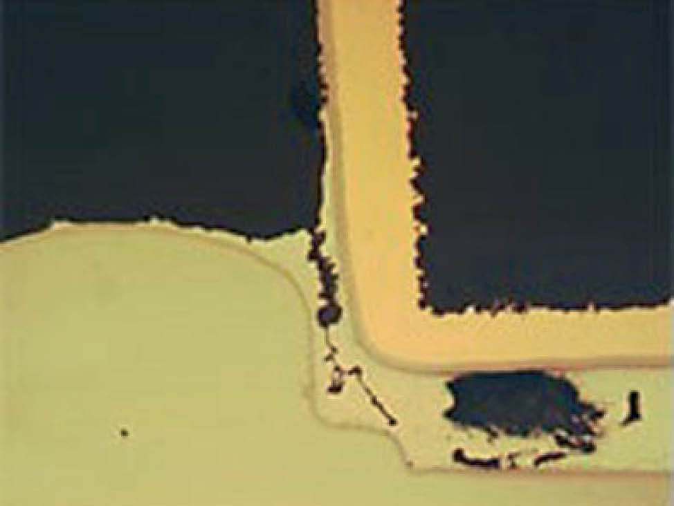
Fig. 10: Void and crack in the solder connection of a plated through-hole (200 x)
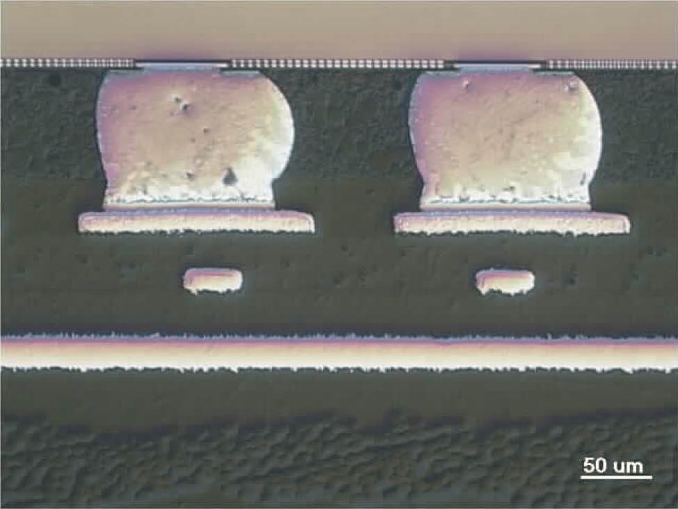
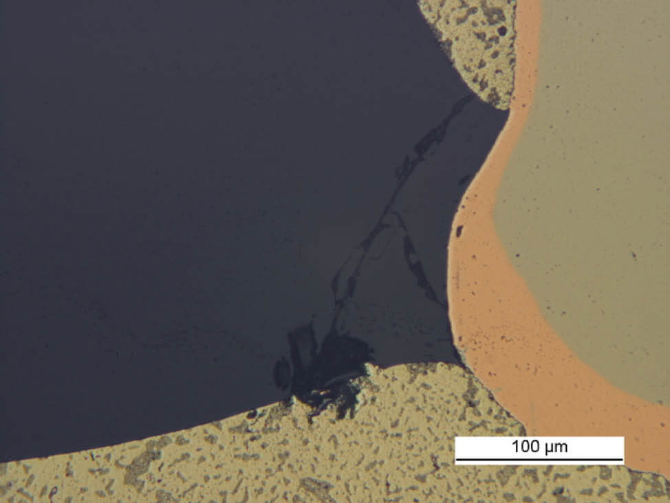
Fig. 11: Cross-section of solder balls, DIC


